New CNC Build
I'm putting together an XZero CNC machine & learning as I go. I'll add pics as work progresses. Hopefully, this will come together fairly quickly because my shop is now so crowded, I have to go outside to fart. Please excuse any ranting I do. I usually take the pictures when I'm forced to quit due to some glitch & I express my frustrations here.
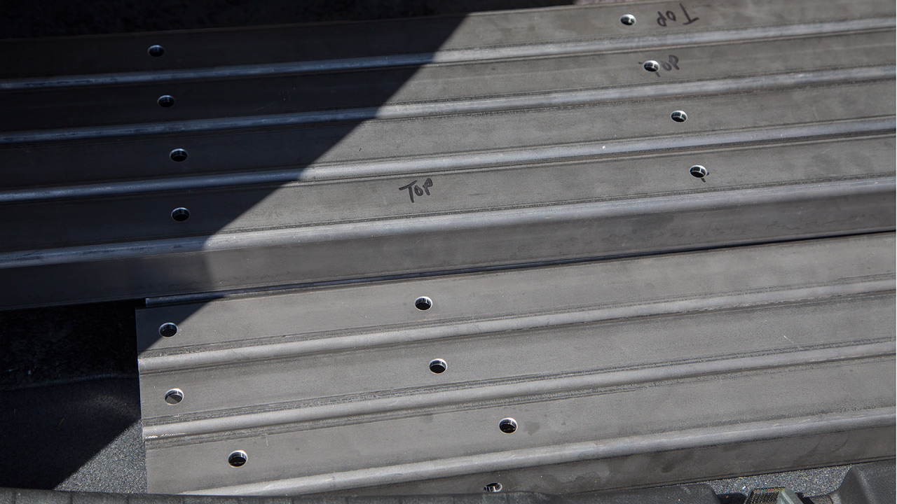
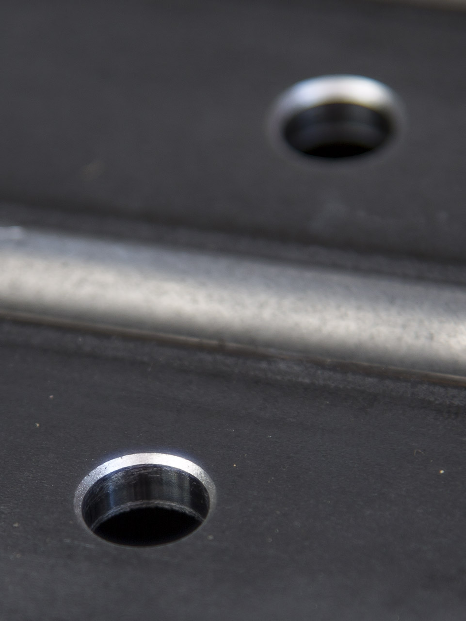
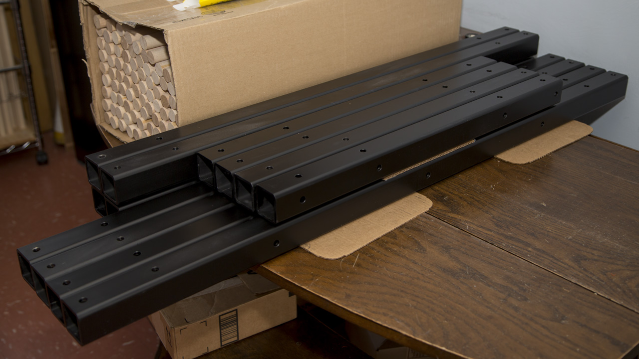
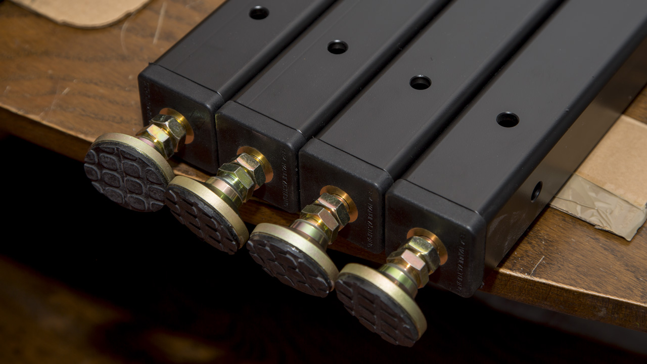
While I'm waiting for parts, I got some heavy wall tubing to build a frame. The corner brackets will be coming from XZero but I have to provide everything else. I bought the tubing locally & my son, Matt, put in all 168 holes. (Thanks, Matt!) A black epoxy powder coating was applied over a gray powder coat primer. Finally, the leveling feet inserts don't come in a size to fit this tubing so I machined them on my Techno to fit.
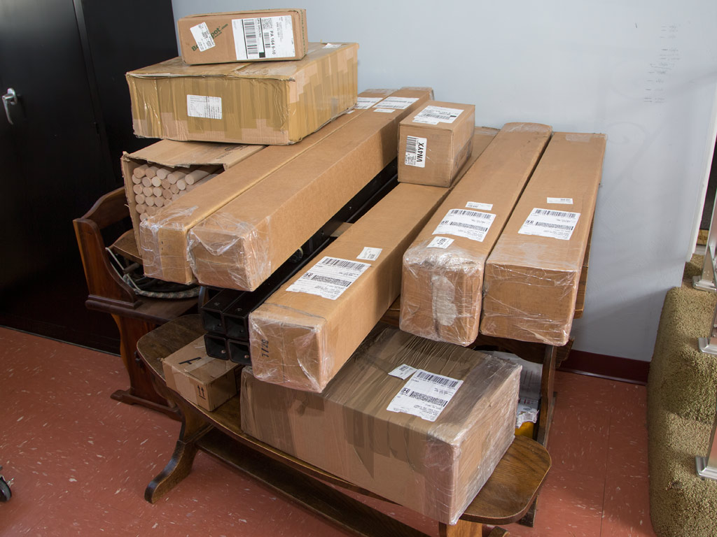
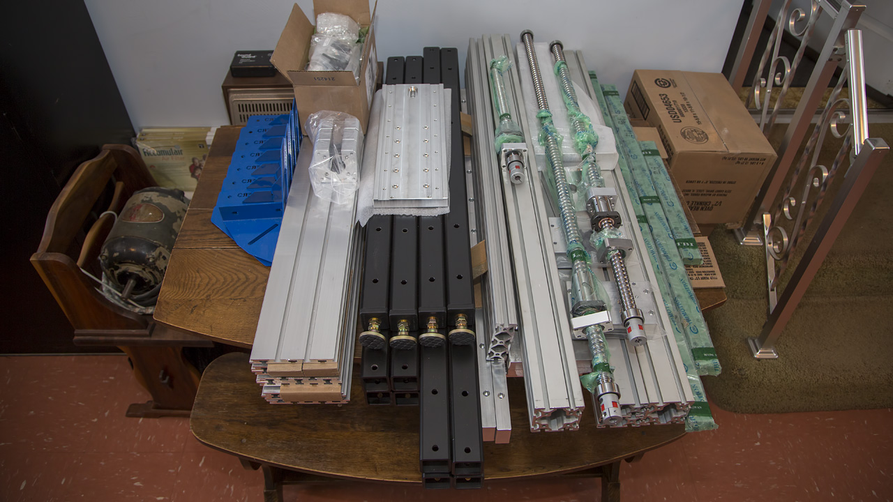
Most of the parts came in but I still don't have all the bracket corners.
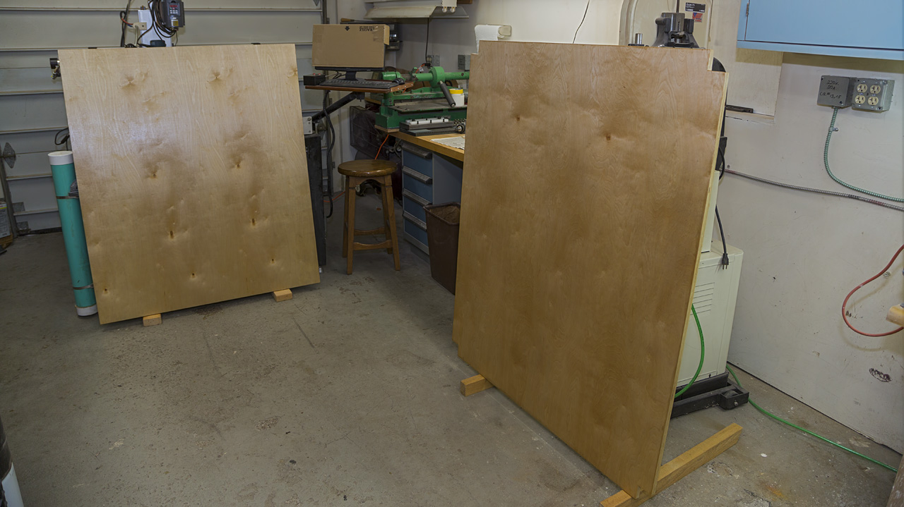
Plywood shelving for the frame is getting some clear poly.
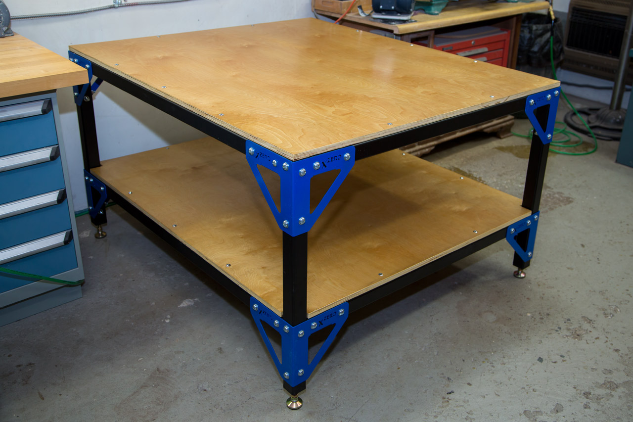
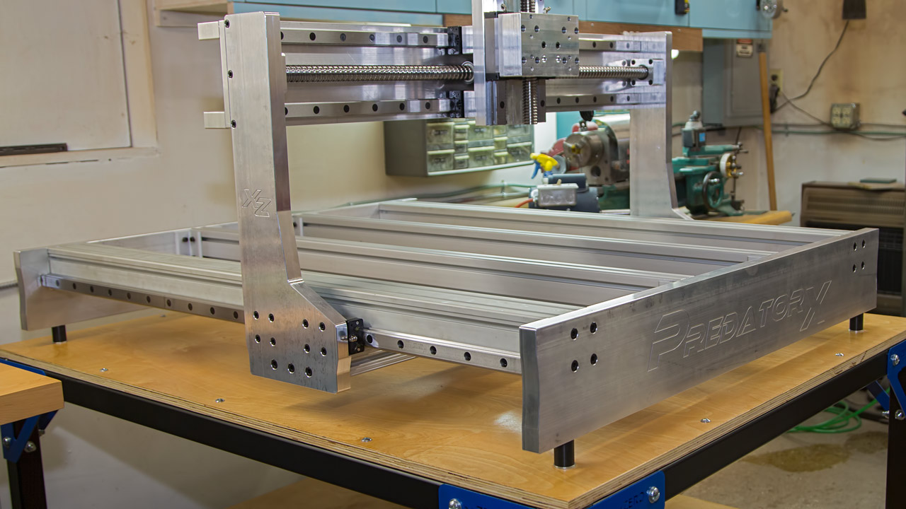
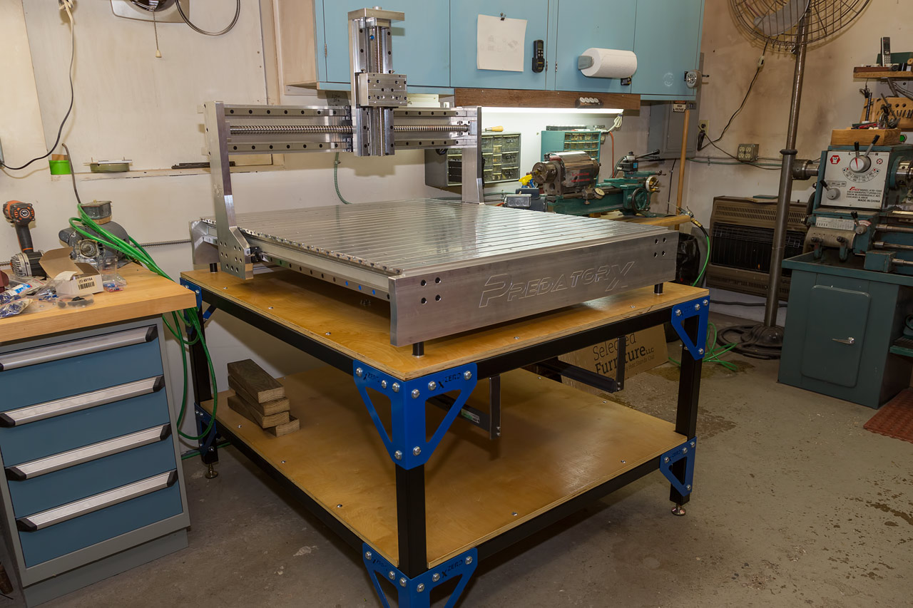
Now that the wood is dry & brackets in, the frame can be assembled complete.
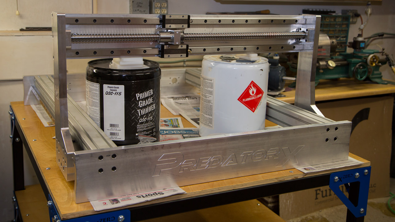
Starting to go together. 5 gallon containers help support the gantry during assembly. I have to stop here due to metric hardware shortages. I can understand mistakes in packaging but a "brace kit" should include the hardware needed to install the braces. I've already cleaned out every hardware store within 5 miles.
Assembly instructions & a packing list would make things easier.
I doubt that I'm the first person to say that.
Serenity now.
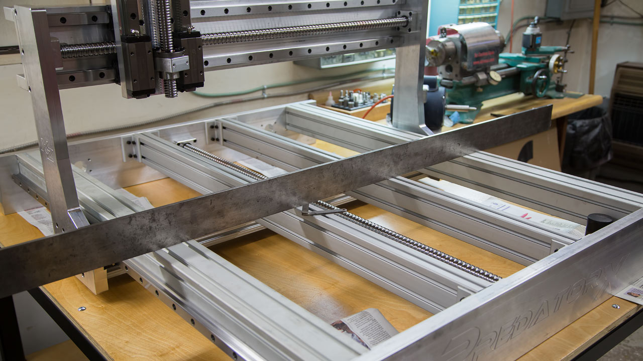
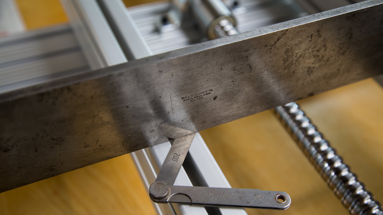
Got my screws & flat washers to install the brace kit. I used a 6' straightedge to see if it was possible to align all four extrusions and it came out pretty well. Worst spot had a .002" dip for about a foot. I'm going to have to remove the front frame piece to insert the table top mounting nuts (whenever they arrive). That means I'll have to align it once again but it's not a big deal. Still not sure if I'm going to let it sit flat on the plywood, bolt it down to the plywood or install 4 leveling pads to gain some height.
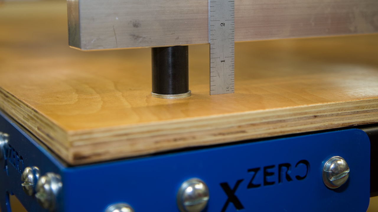
Update: as you can see, I decided to bolt the machine to the plywood but raised it with some Delrin spacers.
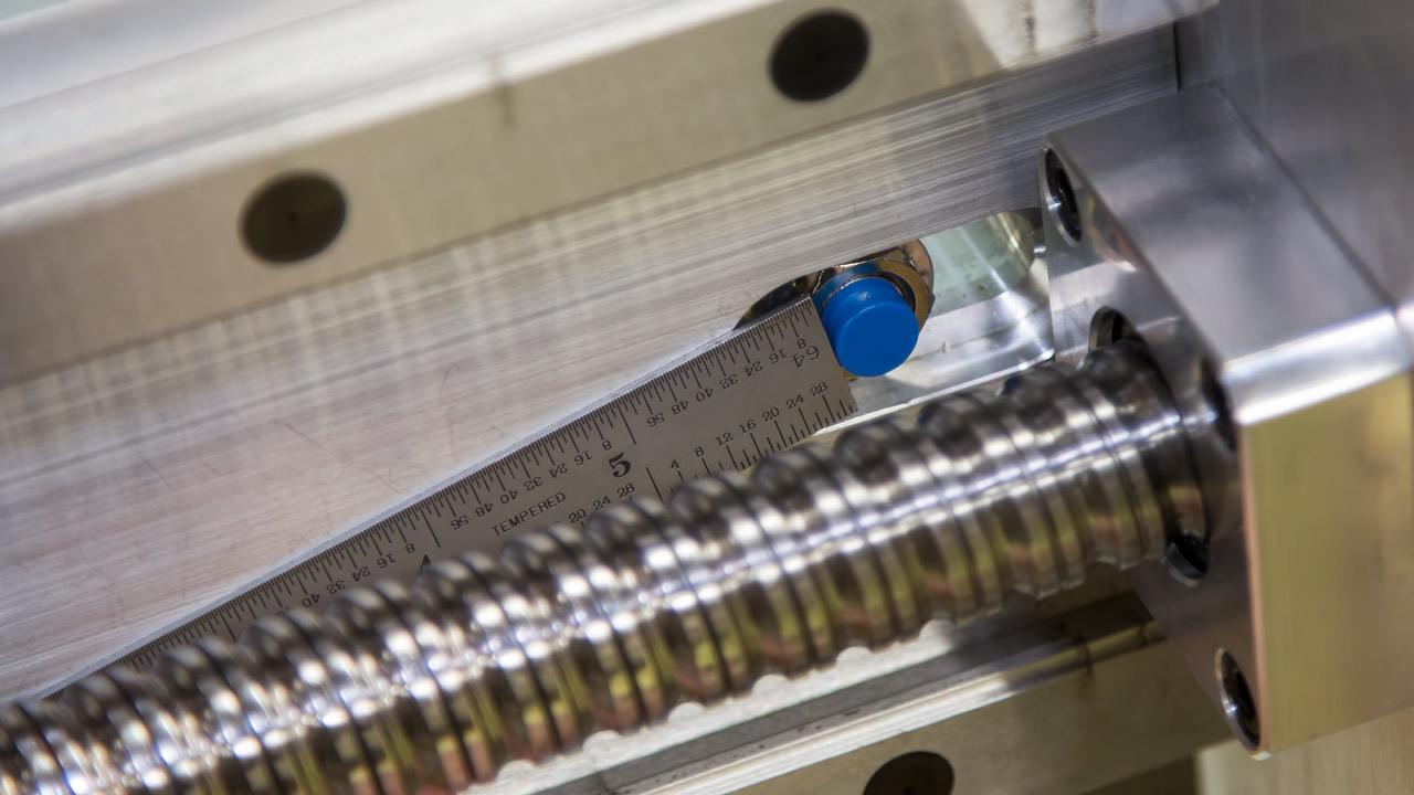
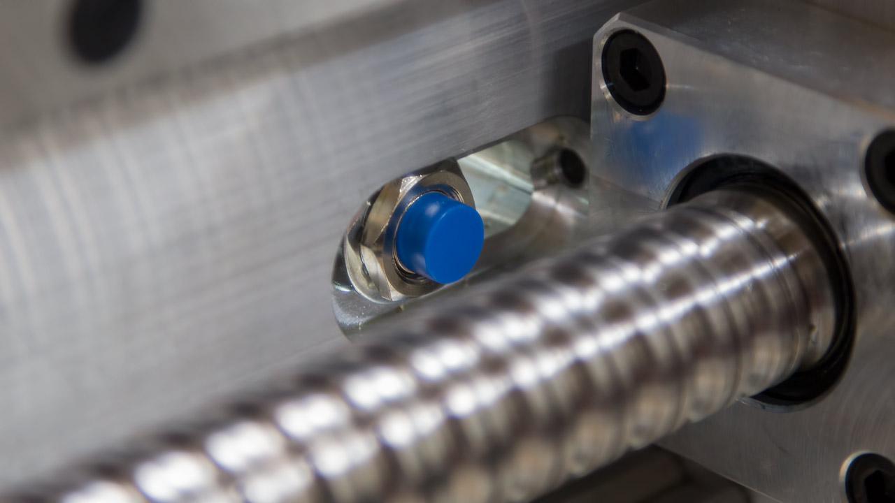
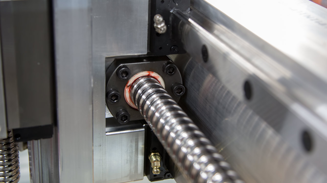
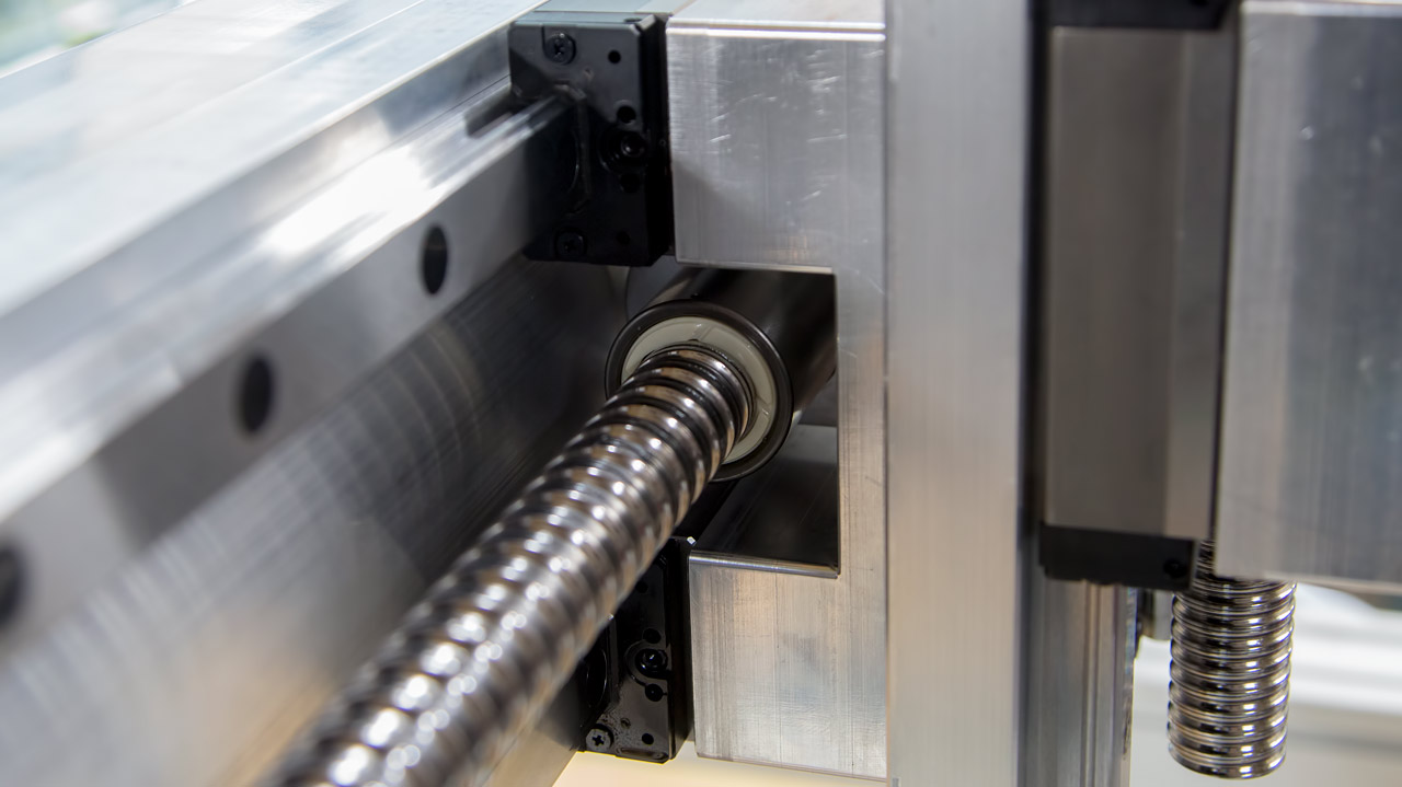
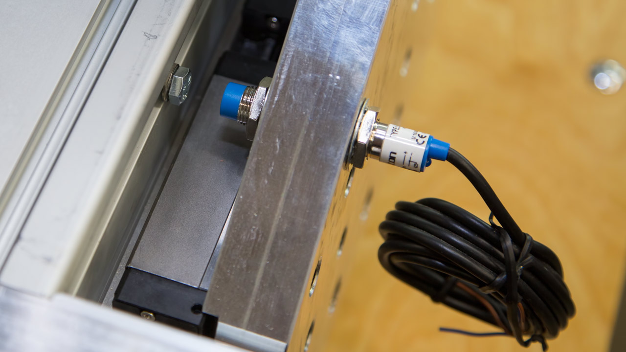
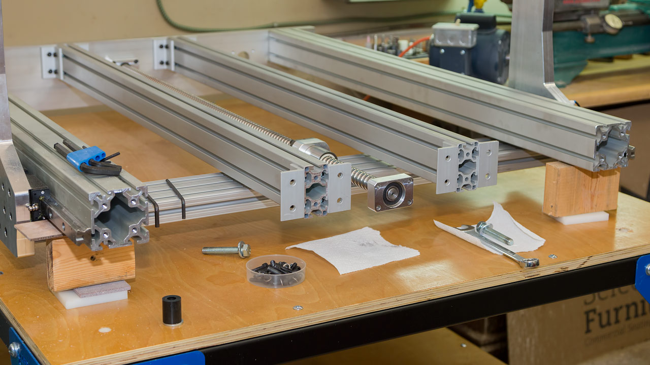
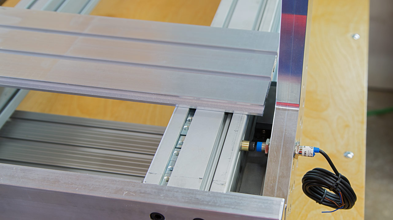
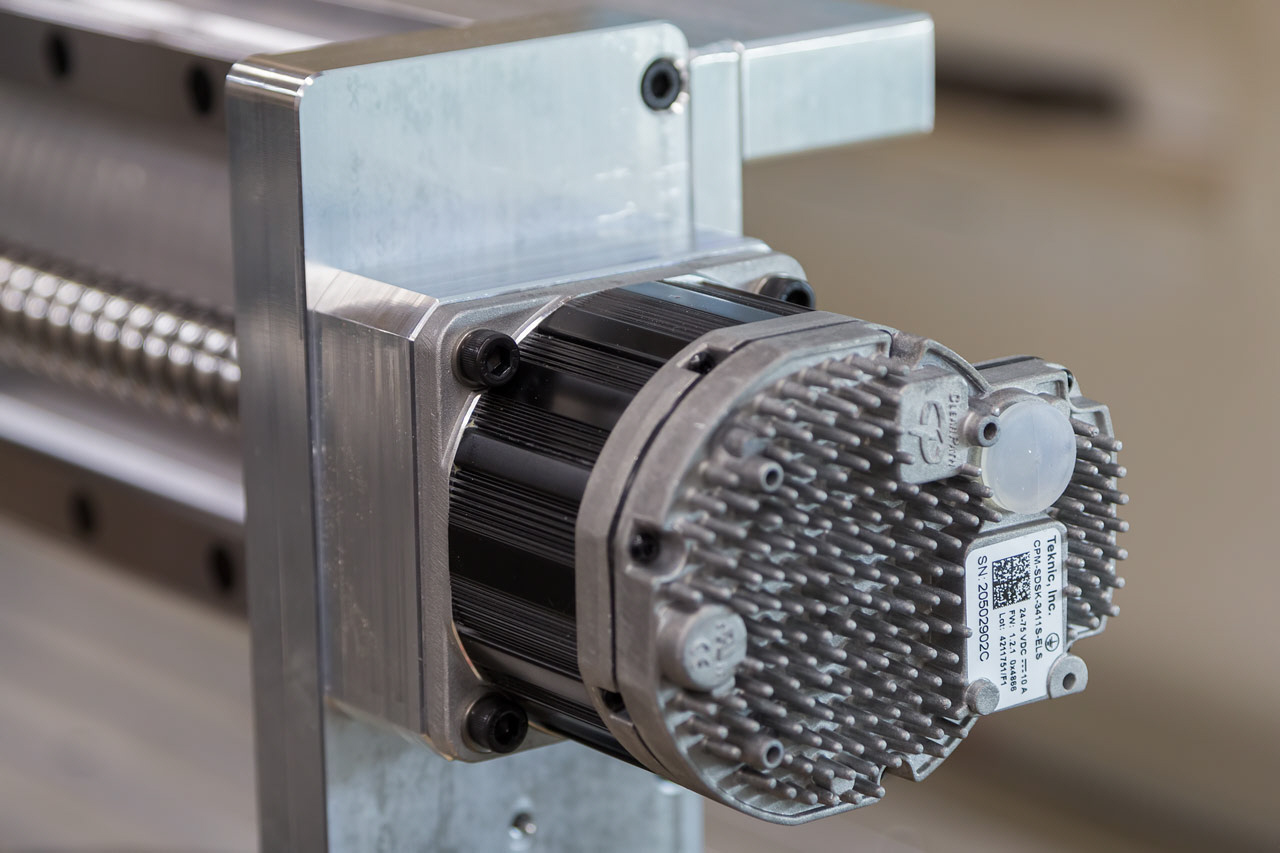
Trying to figure out these proximity sensors. The sensors on the gantry are set as deeply as possible - you can see I'm barely holding on one thread - but the one on the right will hit the bearing housing (3rd picture from the left). The one on the left will clear because the other side of the bearing housing isn't as large (4th picture from the left). Contrast this with the sensor for the Y axis: it is extended as far as possible and there's still almost 1/2" clearance. I don't know how close these need to be for them to work. The instructions are printed in something that closely resembles English but it's not like anything I ever learned in school. Since I'm at a standstill right now, I installed the caps that seal the mounting holes on the square rails. Of course, I didn't have enough to finish the job.
I took off the front frame member to access the t-slots. All I can do is wait...
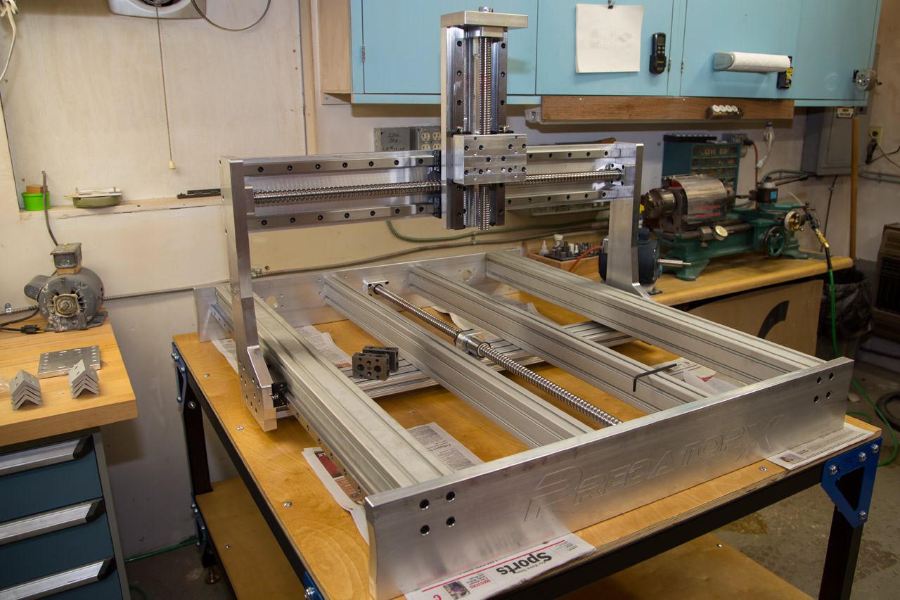
OK, t-nuts arrived & slid into slots. Front frame member bolted back in place & extrusions aligned again. I made brass extensions for the proximity pick-up points. I guess that might help. One of the table top sections is laying on the extrusions. My next project is to drill & CB the sections so they can be bolted to the extrusions.
----------------------------------
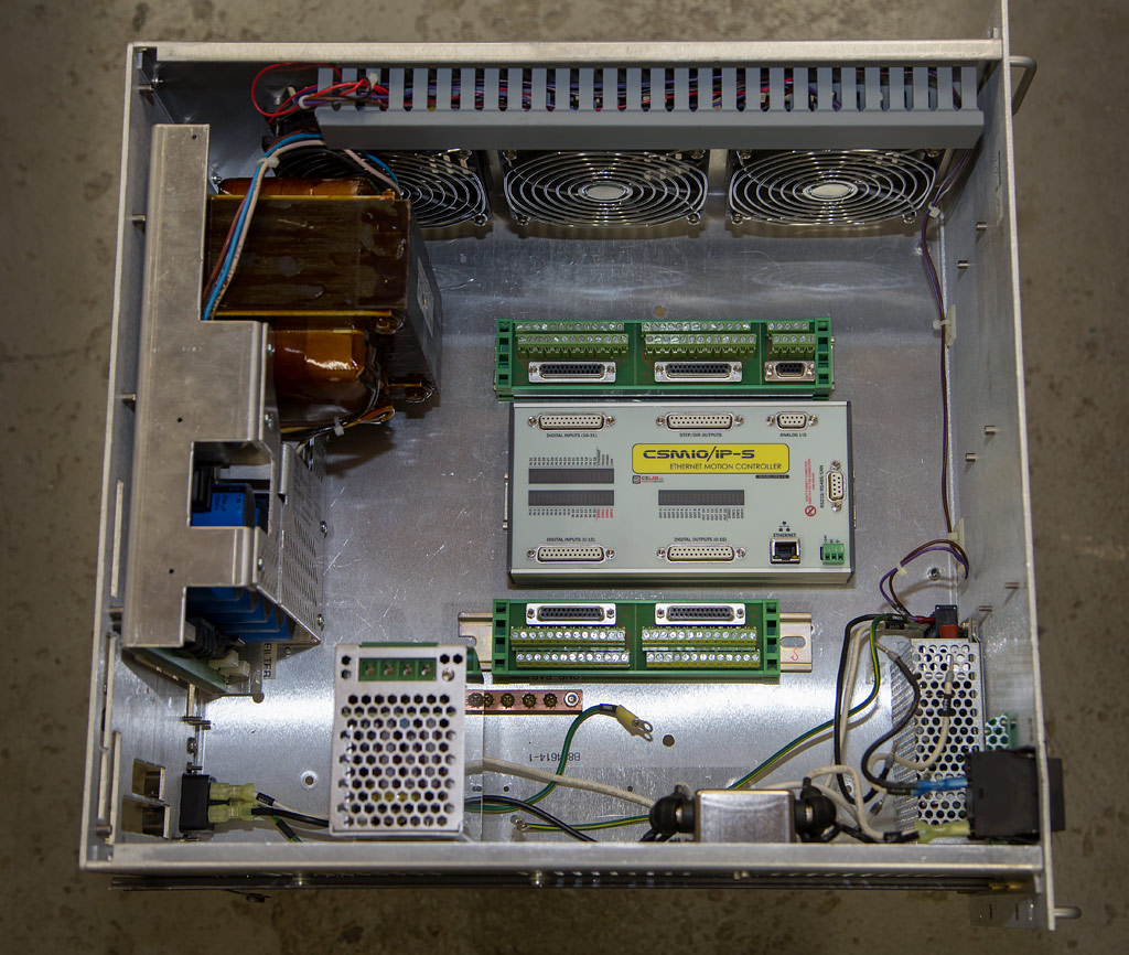
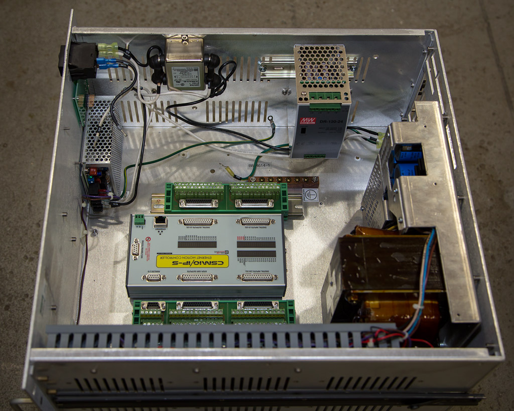
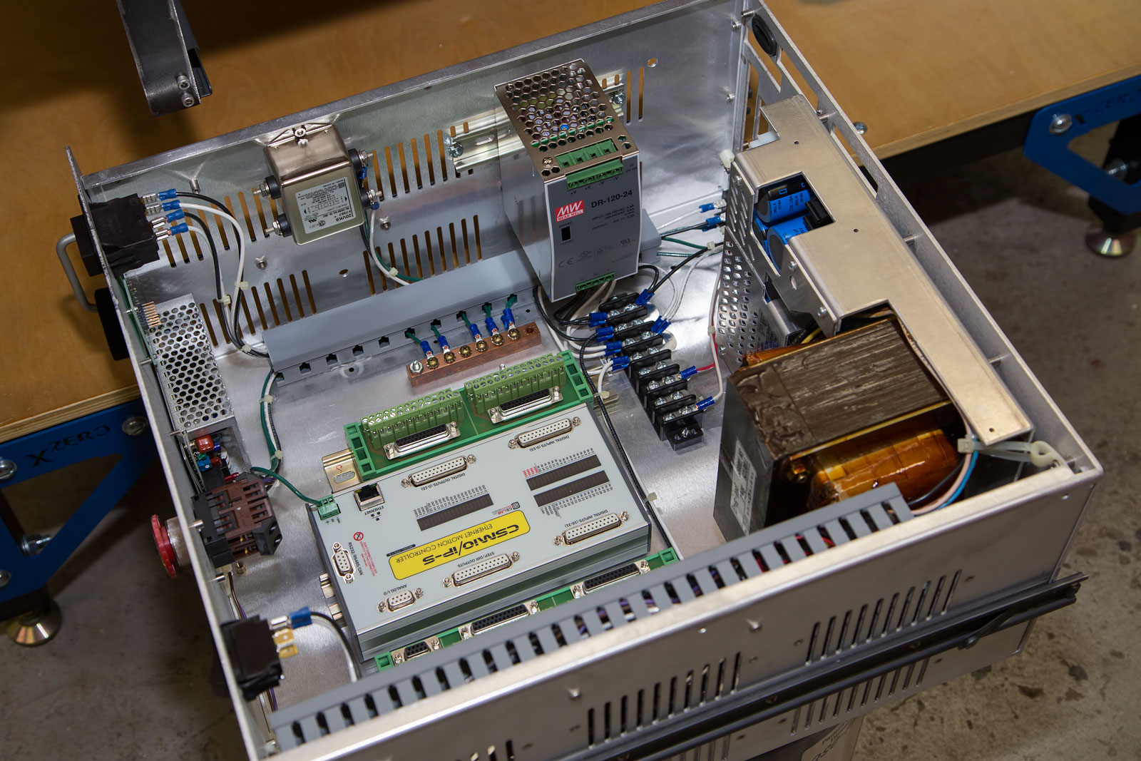
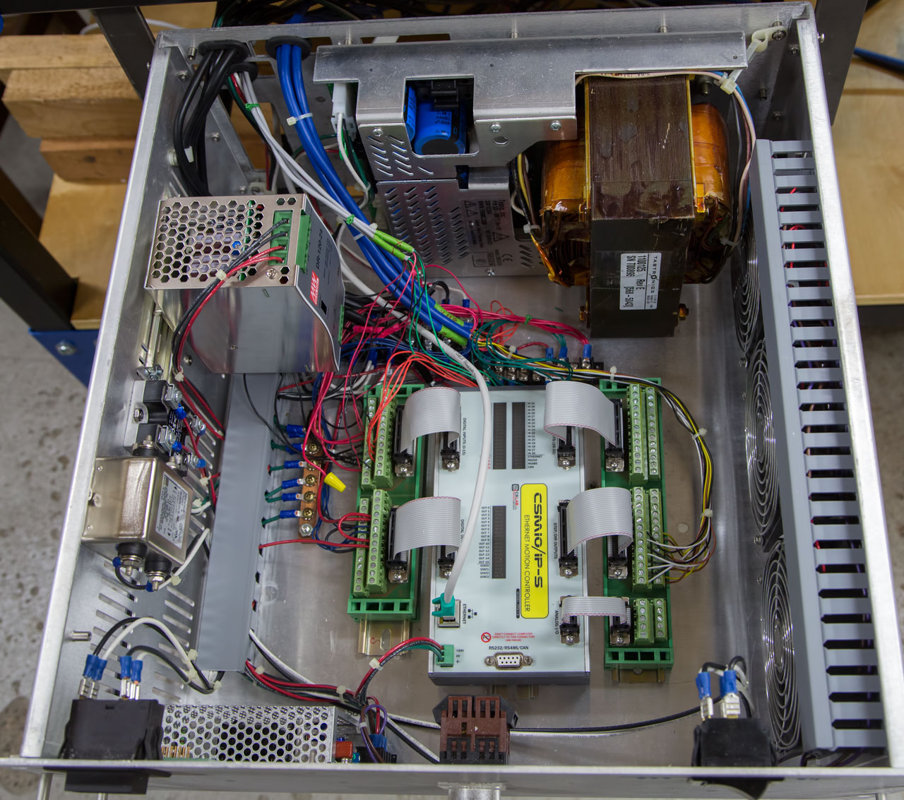
Here's the drawer-type enclosure I'll be using for the electronics. I think everything is in a good place now. I can access all the terminals & connections and I believe the ventilation will be good. Now to wire it...
-----------------------------------
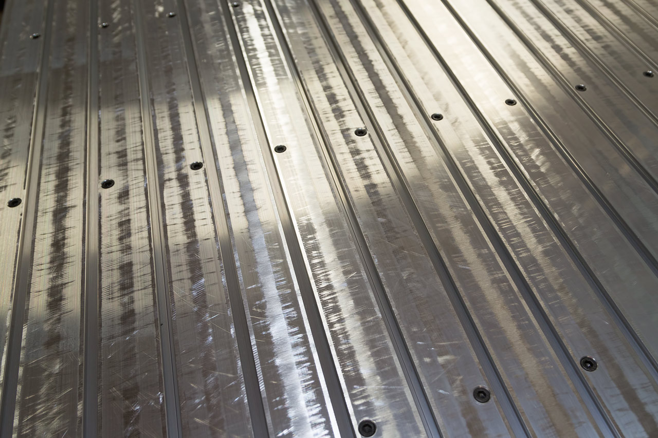
Finally got the table top mounted. The extrusions are of a soft aluminum and were not very flat. Although the bolts drew them down (to a surface that was, itself, not very flat), I filed the top surface to bring down the high edges. Also installed the drawer slide mounting brackets for the electronics enclosure (front of machine, under the frame tubing). They are surprisingly sturdy. Still dealing with the wiring.
The basic 220v input power has been wired. Gotta get a handle on wiring the e-stop but I think that will come along with wiring the motion controller. More on that later. I'm getting EXPERT advice on this!!!
-----------------------------------------
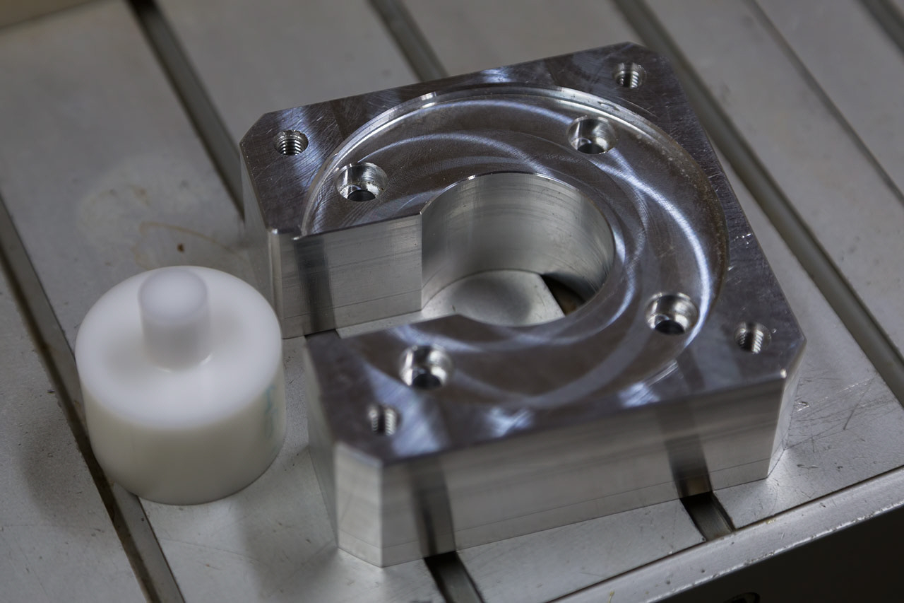
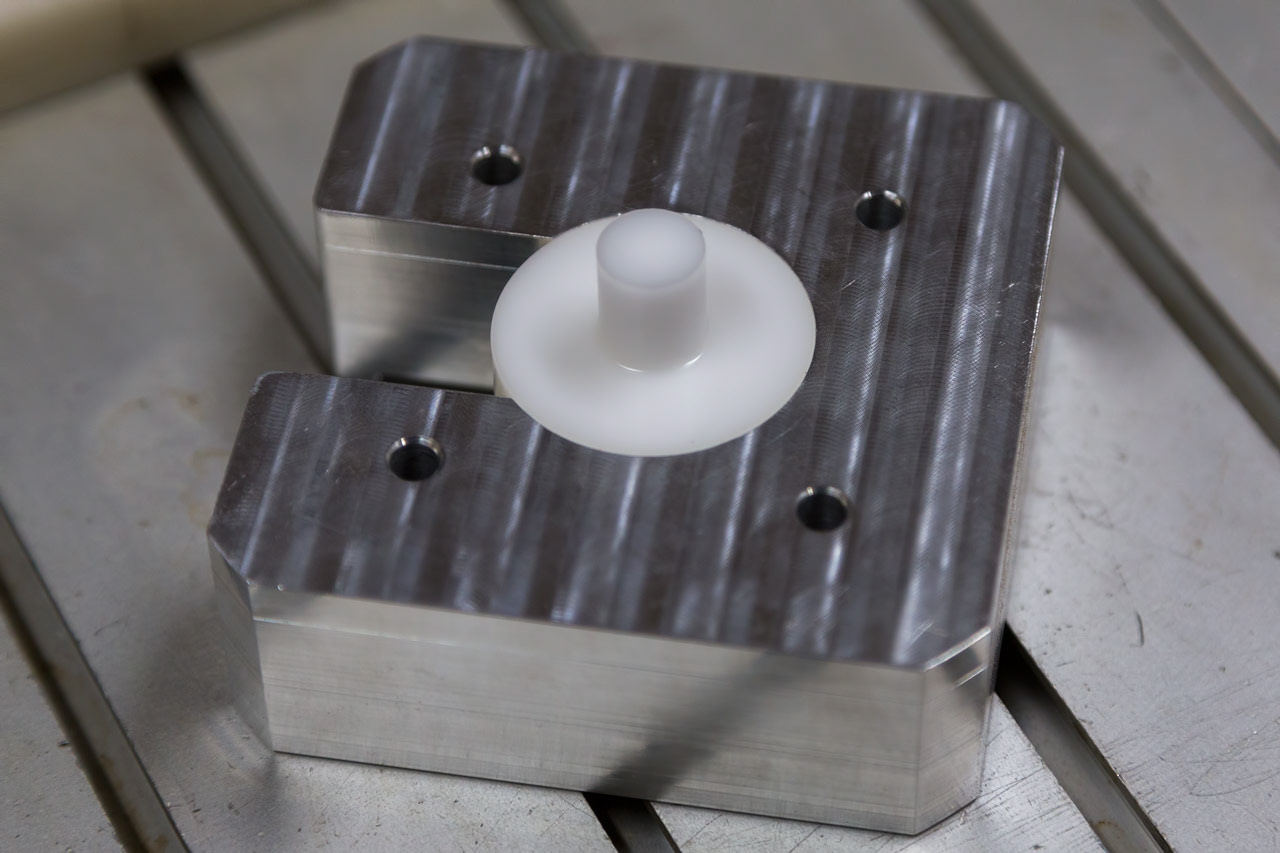
I had to shorten the motor mounts & bolts to accommodate the ClearPath motors and when I went to install them, I was disappointed to see that once the motor was attached to the mount, there was no way to adjust the alignment with the coupling. I made a little Delrin alignment tool that closely fit both the coupling & the inner diameter of the motor mount. This made sure that the mount was concentric with the coupling when it was bolted down. This gave me more confidence that when I installed the motor, it was going in the right place. It slid into place perfectly!
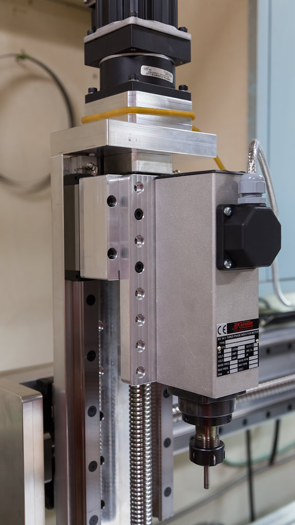
A lot has happened in the past week. I had to make a new, longer mount so my spindle would reach the table. But the real progress was in the wiring. Thanks to some expert advice and generous assistance, all the details are being ironed out. The machine is now running & I'm dialing the mechanical parts in.
Here's a LINK to a video showing the first programmed movements of the machine!
I glued 2 pieces of 1/2" thick corian together for a scavenger board. Once the epoxy set up, I cut the back side flat on my Techno. Then I took it over to the XZero & cut it square & put in the holes for mounting it. When I went to mount it on the XZero, I found 2 issues: the first was that my tabletop sections weren't very square with the machine. I had to loosen all 64 bolts & shift one end about 1/16".
The 2nd issue came when I tried to indicate the scavenger board. The y axis was pretty good but the x axis had some crazy variation. Granted it was all within .005" over 30-some inches but after everything else checked out so nicely, it was a bit of a disappointment. I pulled the backing bars to make sure there were no burrs or dirt that could be distorting the gantry but they were ok. I suspect that mounting the square rails to their pockets in unmachined 6061 aluminum bar stock is the root cause but I don't really see it as a big enough problem to worry about.
Here is a LINK to a video showing the axis check.
In dialing in the z axis, I had to shim the z slide slightly to get it to travel square to the corian. Of course, this threw out the relationship between the spindle and the table so I had to shim the spindle the opposite way. Once I had everything trammed in, I cut the surface on my corian scavenger board & double checked the z axis once again. It was close enough that I'm happy with it. For the record, the z slide is perfect in the x axis and within <.001" over 4" in the y axis. The spindle trams square to the corian surface within .001" in a 10" circle.
-----------------------------------------
I tried homing to an indicator and was pleased with the results as shown in this video.
-----------------------------------------
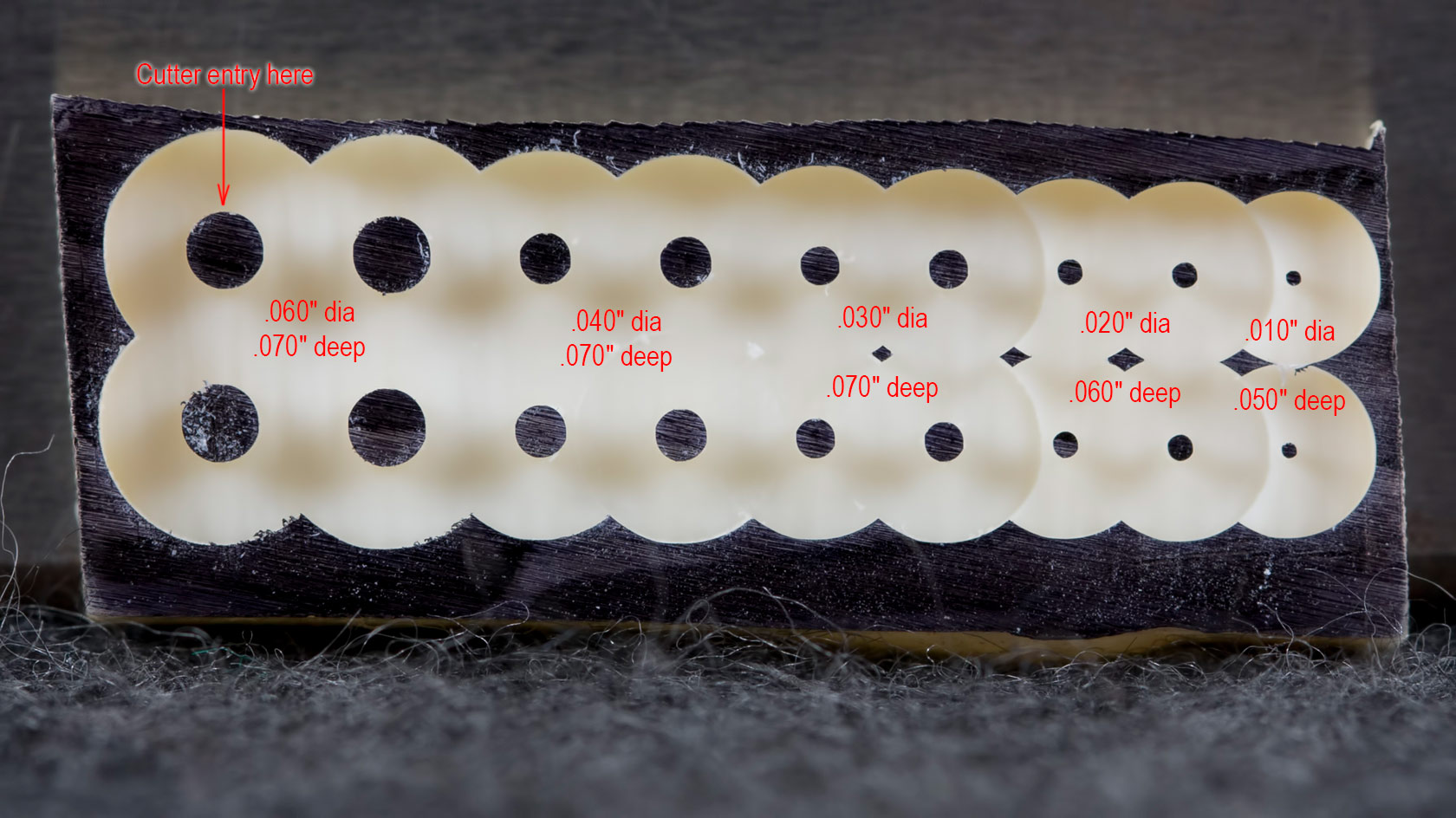
Here are some test cuts. I'm trying to leave little "islands" that will show how round the cuts really are.
And as well as this worked, it also bears witness to the smoothness & accuracy of the spindle!
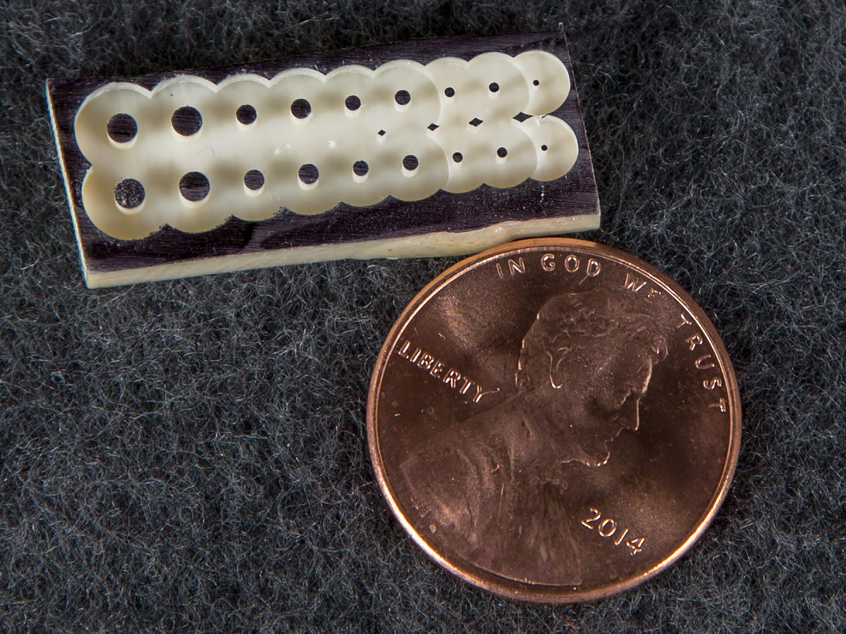
To better put these little pins in perspective...
I can't believe I was cutting an "island" .010" diameter that was 5X that deep.
Maybe there's hope for this machine yet!
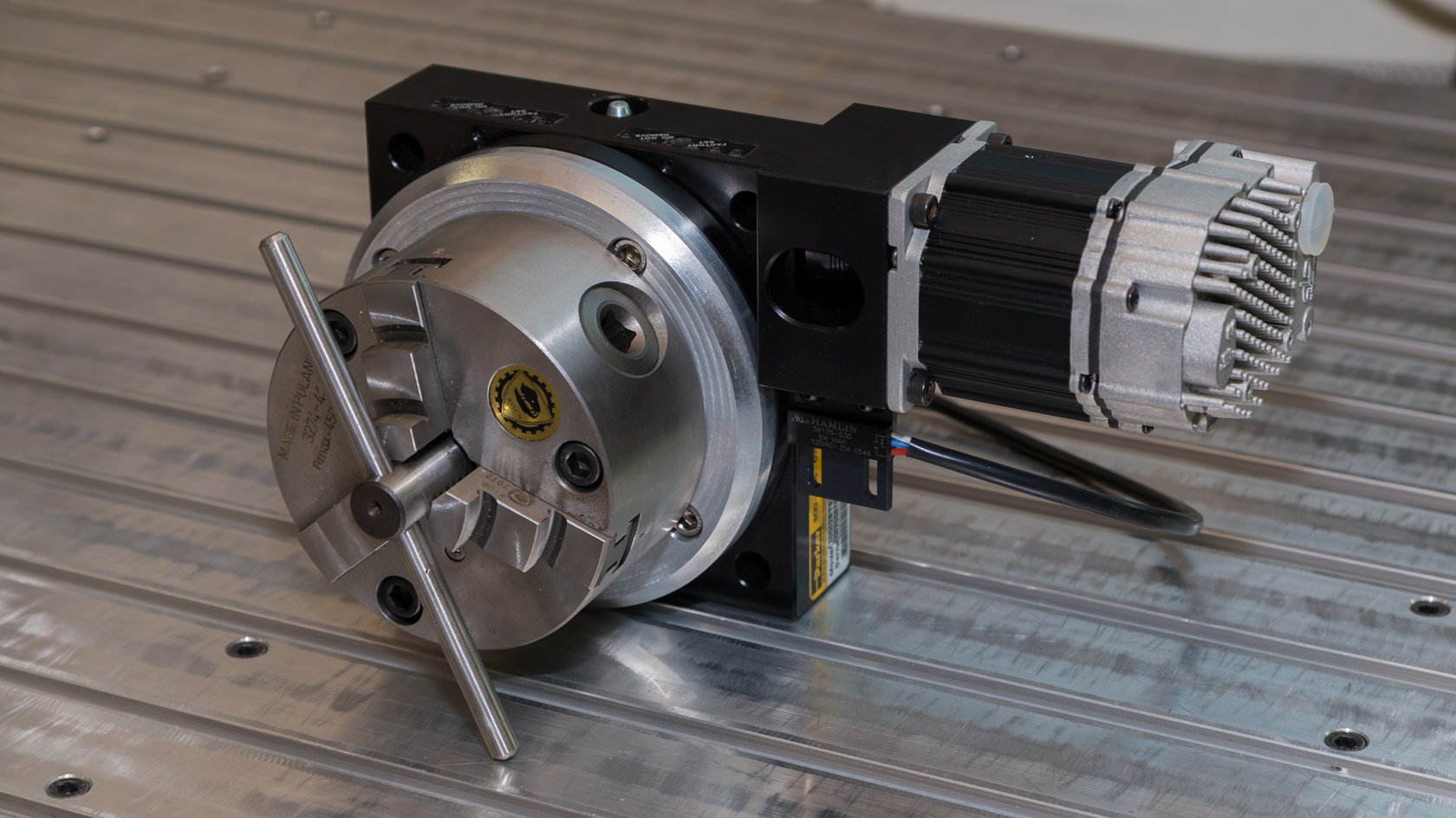
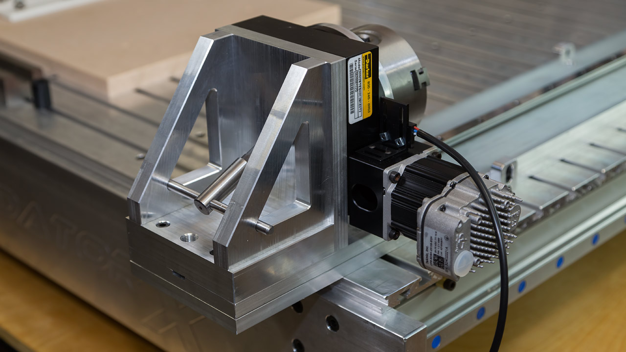
Getting the chuck mounted to the rotary table. Next will be mounting the rotary table to a set of uprights which will then be mounted to a fixture with a movable tailstock. Then I'll be able to put this puppy to work.
One disappointing thing I learned while designing the fixture was that, despite my machine's 40" x 48" table size, the working range of the machine is not 36" x 40" as is advertised. It is actually much closer to 32" x 36". I can gain another 1/2" if I remove the grease fittings from the bearing blocks but it's still shy of the advertised travel.
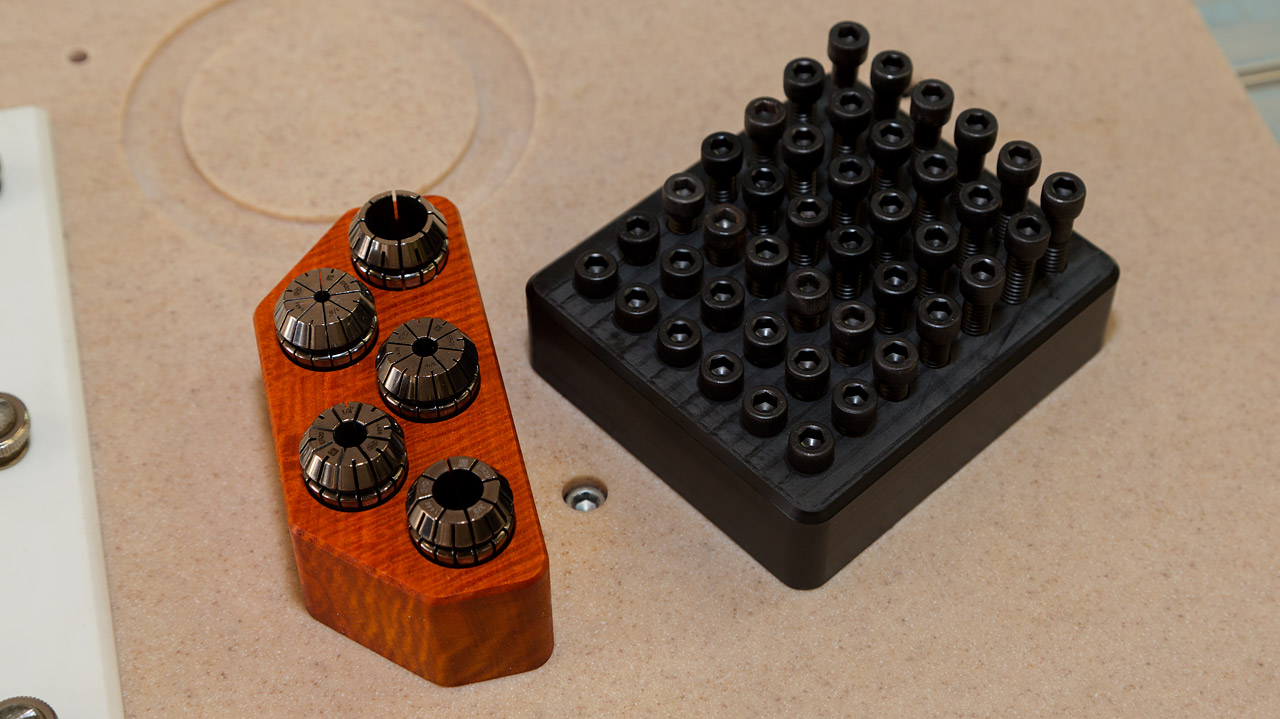
Still awaiting some parts but I'm getting familiar with the machine by making a few odds & ends. Here's a bolt caddie and a holder for my commonly used ER20 collets.
-------------------------------------------------------------------------------------------
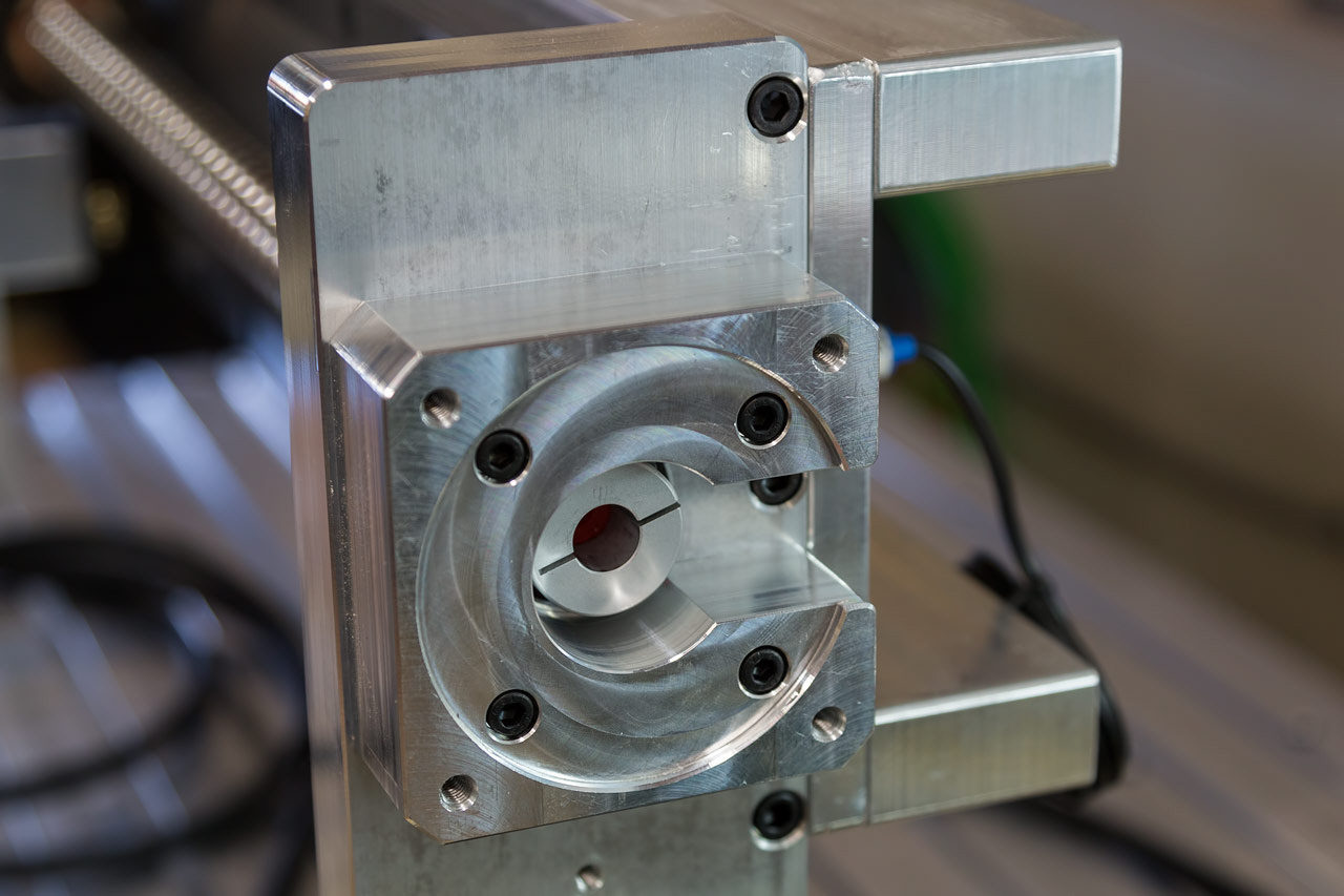
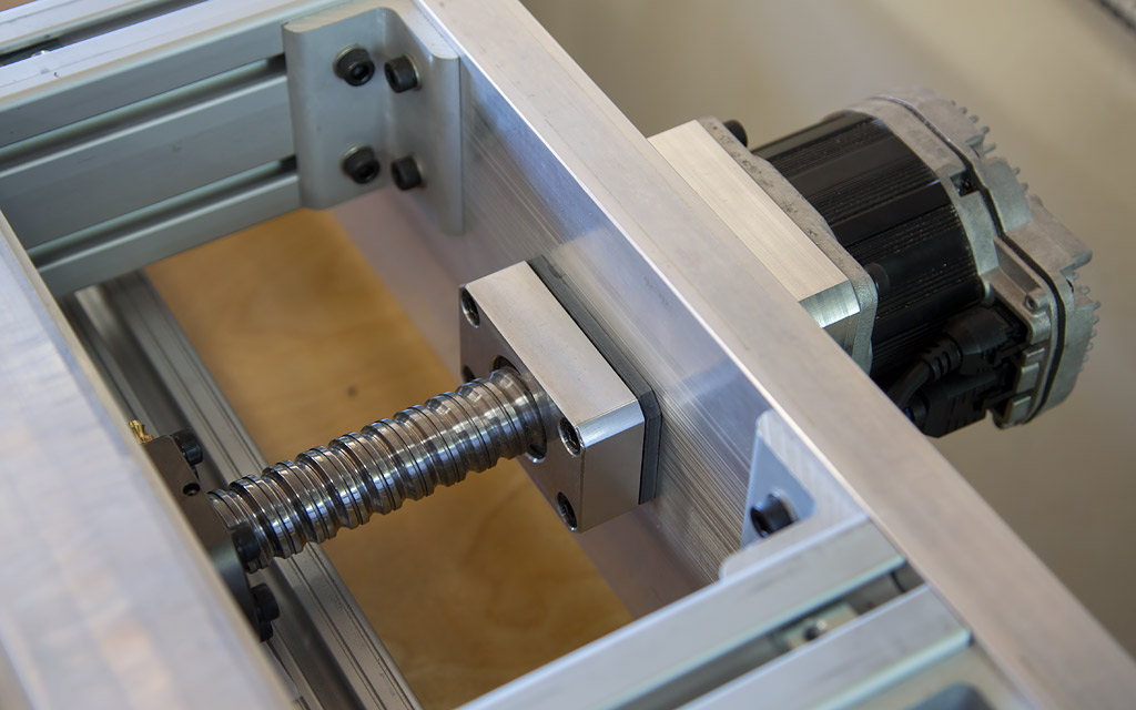
I was disappointed to find the Y axis had about .0006" backlash compared to the .0001" backlash in the X axis. That accounted for the slight football shape of the small islands cut in the test shown above. George was gracious enough to provide me with a new Y axis ballscrew that proved to have less backlash than the first one. It arrived the other day & I was pleasantly surprised to see a bearing nut retaining the AC bearing vs. the clamp style coupling used on the original ballscrews. Unfortunately, the ball screw was shorter than the original by almost 1/2". About 1/8" of the error was from the floating bearing diameter being 1/8" longer than necessary & the remainder was from turning down & threading the other end of the screw for the retaining nut threads.
When mocking up the assembly, I realized the floating bearing was sticking out of the bearing housing by about 3/8". This isn't good when the bearing is only about 1/2" thick. I made a 1/4" thick phenolic spacer to put behind the housing to recover some of the lost length without forcing me to order longer screws. However, by moving the screw in that direction, the motor would bottom out in the coupling while it was still over 1/4" from the motor housing. To solve this, I swapped out the 1/4" spacer & put it between the AC bearing housing and the frame, then made a 1/8" thick micarta spacer to fit between the floating housing & the frame. This allowed the motor to fit where it should & also seated the floating bearing completely in its housing.
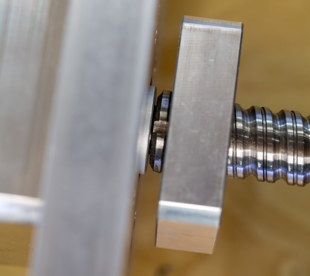
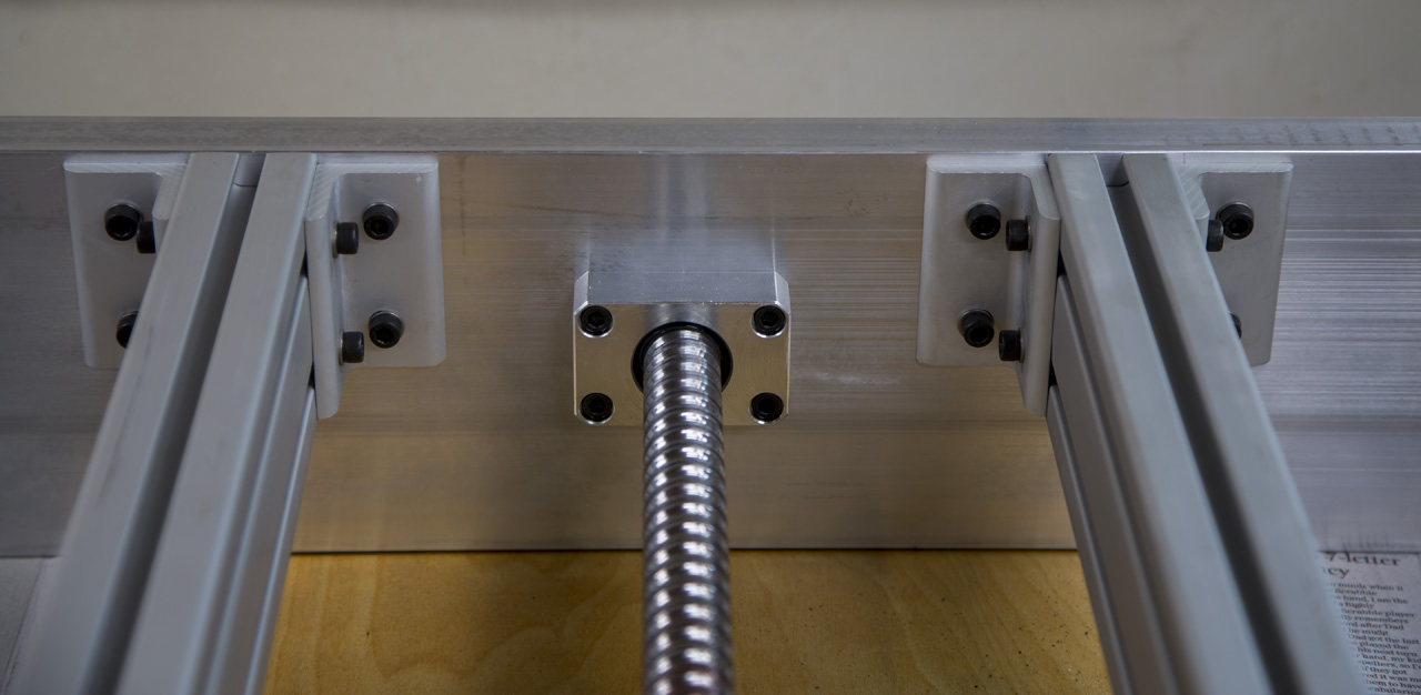
In this view, you can see the retaining nut between the coupling and the AC bearing housing.
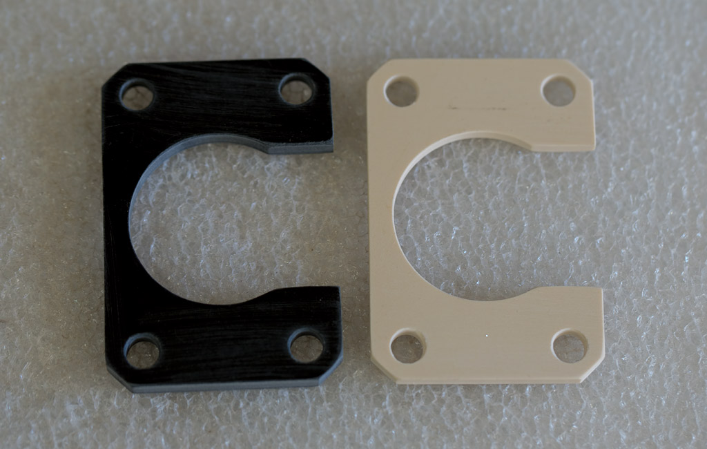
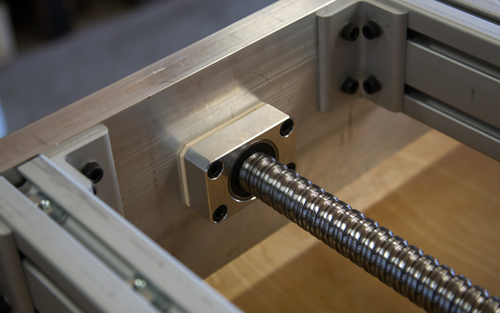
These are the two spacers I made to slip in place as described above. You can see that the floating bearing is now flush with the housing & the motor is now mounted in place on the other end.
This change-over meant removing my fixtures, much of the table top & also the front frame section of the machine. I've since reassembled and aligned everything, tuned the motor and installed & resurfaced my scavenger board. Initial tests show that the new ballscrew is tighter than the original so I'm happy with that.
Another quick video (1 minute), similar to the test from above, cutting a series of .020" diameter islands. They're not perfect but I'm content with the results. Keep in mind that a human hair is about .004" in diameter.
It would be interesting to see the results of this test performed on other machines. I have no idea how my machine stacks up against any of the other commonly used machines: K2, Shark, ShopBot, etc. The exact G-code I used can be downloaded by clicking on THIS LINK for a fair comparison. If you do this, please let me know some details about your machine, motors, screws, rails, spindle, etc. I can post a link to your video, too, if you'd like.
---------------------------------------------
OK, time to cut wood! I had an idea for a 4 piece inlay last year that I was eager to try out. I had some left-over veneers that were perfect for the job so I put the XZero to the task of cutting them out. The veneers had black paper on each face & I wanted to make sure the inner face would be saved. It cut them better than I expected!
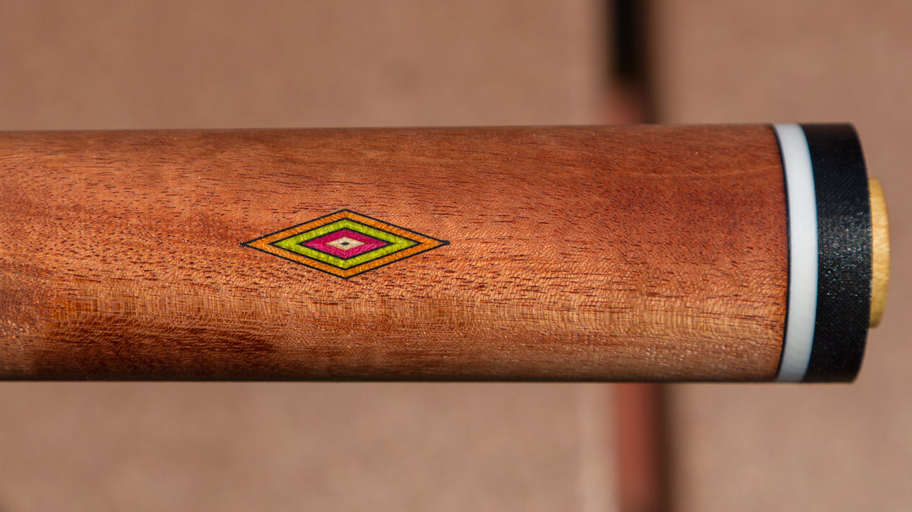
Here's a picture of the inlay. And, yes, you can see the black paper in the center! To get a sense of its size, the inlay is 1" long, The veneers are .9mm and the black paper is .008" thick. I am very happy with my XZero!
Another test of the machine's capabilities is shown HERE doing some external threading. Very neat stuff!
---------------------------------------------
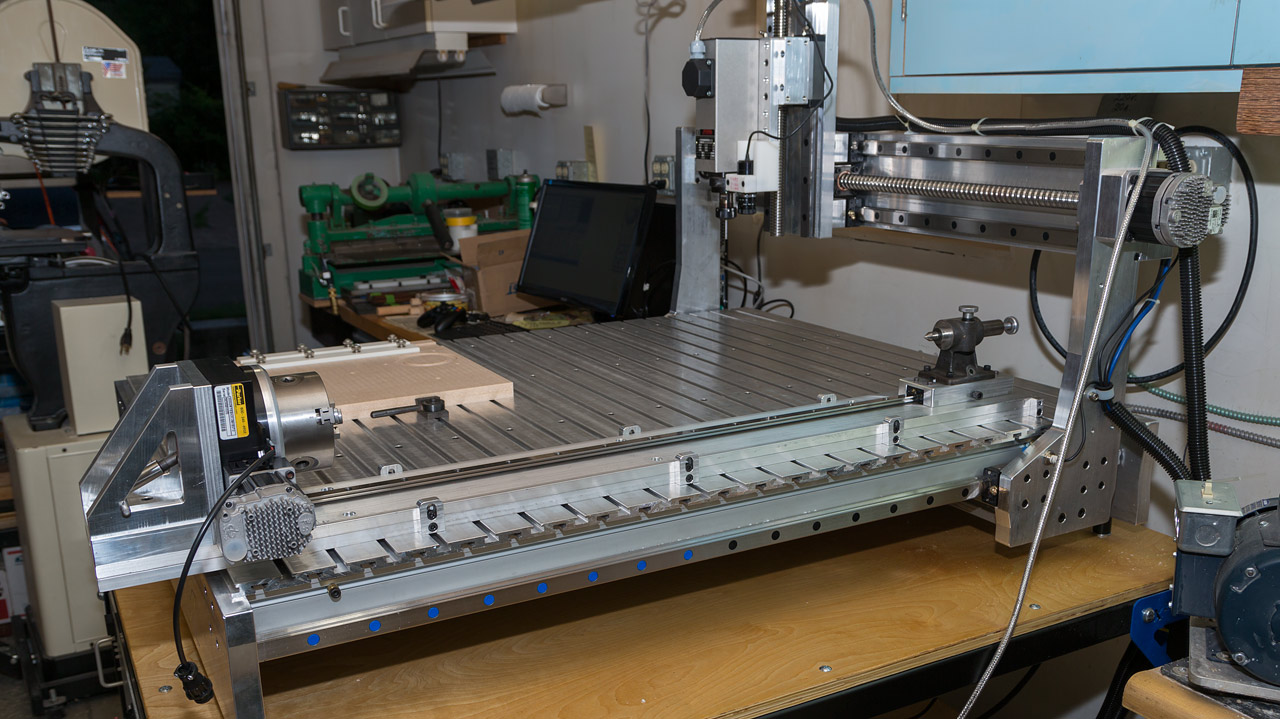
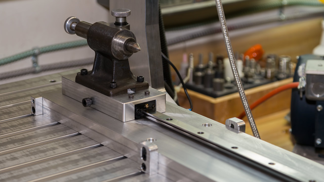
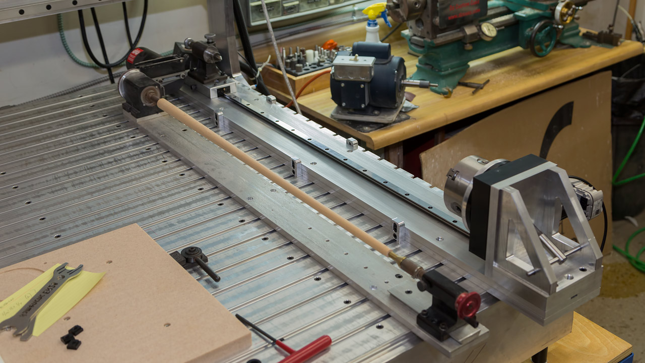
Matt finished my indexing fixture & it looks great. Part of it needs to hang over the end of the table so I can reach a complete butt section supported between the 3 jaw chuck & the spring loaded center. A nice feature of the center is that the main barrel can be moved at least 2" giving me a lot of travel without moving the tailstock. The tailstock rides on a square rail with linear bearing blocks. The fixture, as shown, has the centerline level for billet work & cutting V-grooves. After loosening the clamps on the side, I can jack up the rotary table end with a fine thread screw until the top surface of the butt is level for inlay work. I recently made a tapered Delrin wedge to slide between the plates to get the cue close to dead level. It's a time-saver! My old shaft turner is scrunched up next to it to save as much space as possible. I'm anxious to get everything lined up & try them out.
----------------------------------------------------
After tuning the A axis motor & verifying that it was working correctly, I had to figure out how to do some basic indexing. I relied on old memories of main & sub programs & was able to get working programs. After a few tests, I was ready to give it a try. In this video, I show a program in which the cue indexes to one location, cuts a pocket using one program, then it indexes to the next location & cuts a mirror image pocket using another program. Then, it repeats that pair of programs 11 more times. SO much easier than manually indexing with my spin indexer!
--------------------------------------------------
(Note to everyone: Despite 18 yrs with my Techno, I had no 4th axis. I know nothing about 4th axis programming.)
Here's my first attempt at a practical application of 4th axis "wrapping". This is known as "axis substitution" because the spindle doesn't move in both the X and Y directions. It moves only in Y but the chuck rotates in place of the X axis. Pretty cool to watch but kind of a pain to get everything working properly.
Another day, another lesson learned!
Here's the result of another test cut I was playing around with. I'll be using this someday.
---------------------------------------------------
I built a new shaft spinner that is more versatile than my original. Here's a sample of what I'm doing with it now.
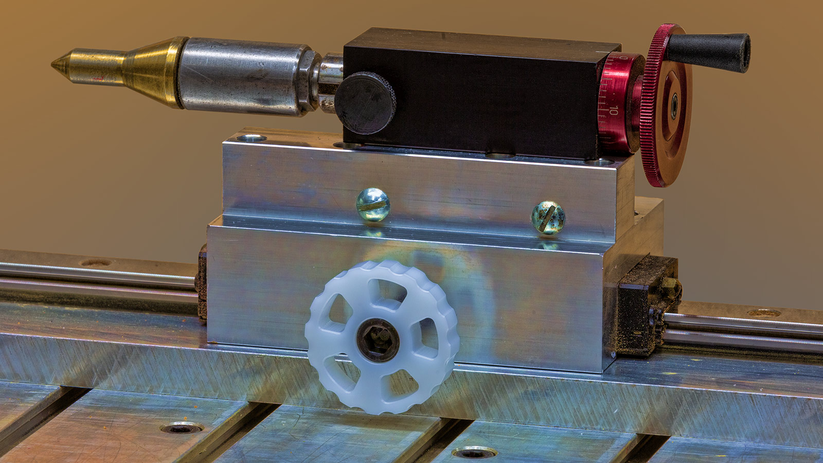
Also, I added hand knobs to lock down the tailstock so a loose hex key wasn't needed.
Looks cool & works great!
--------------------------------------------------
More to follow.